An Arduino-based launcher for water rockets with multiple interlocks and safety features.
BUILD TIME: A WEEKEND
DIFFICULTY RATING: Intermediate
Water rockets are, for most of us, a fun science experiment we did in high school, or maybe even primary. In their basic form, a cork or rubber stopper with a ball inflating needle pushed through its centre, is installed firmly in the neck of a soft drink bottle, which has some water in it.
When turned upside down, the bottle sits on some form of holder, often a plastic container with a hole and slot cut in it. Then, a bike tyre pump is used to pump air into the bottle until the cork gives way, and the compressed air forces the water out. Newton’s Third Law states that the bottle then goes the other way, and will launch at least a couple of stories, but sometimes up to three or four.
While it’s a popular experiment, a lot of people want more. Water rockets are a serious hobby, and some scratch-made fibreglass models have even been recorded reaching altitudes close to 1000m. These run on high-pressure air and involve lots of skill and knowledge. Further down the scale, however, a rocket can still be made using a regular air compressor and normal soft drink bottles. The cork no longer cuts it, however. Some form of static, controlled launcher is needed.
Some use garden hose fittings modified for the task. Others use a cable-tie release widely credited to Australian Ian Clark. Still, others use a metal lever system. While this is the strongest, we avoided it because of the tools and skills needed to work with the metal involved.
Because there are so many ways of doing things, and because we won’t have space to cover in any great depth actually building a rocket, there are a wide variety of links posted in the ‘Reading and Resources’ section. Most of the videos come from three YouTube Channels: Air Command Rockets, an Australian hobbyist; US Water Rockets, an American hobby organisation; and Raketfued Rockets, a group of German students.
RATIONALE
At first glance, our launcher looks complicated, especially in comparison to some of the launchers on the YouTube links provided. To be honest, it is, but ours is intended to fit a different situation. The other launchers used by the hobby groups are used by people who are familiar with the use, operation, and safety of them, in an environment where only like-minded people are usually present.
Our launcher is intended for effectively public use. Things like school science days, youth events, science fairs, that kind of thing. Any situation where a large number of people may be present who are not familiar with the safety procedures, and in some cases, people who may think it funny to try to trigger the rocket early or get too close.
For this reason, we have designed several interlocks and safety systems into our launcher. Some of them can be forgotten or ignored, which is why we have several. All systems involving people have weaknesses. Forgetting to do a certain thing or engage a certain safety device is not uncommon, but forgetting or bypassing all of them is unlikely.
Additionally, using a servo means there need not be a long string trailing on the ground for firing the launcher. Not only are these a trip hazard, but short of hooking a loop over a stake or peg, it’s hard to stop someone firing these prematurely, either out of enthusiasm or malice.
THE BROAD OVERVIEW
Our launcher is made from mainly common hardware or electronics store items, with the exception of the solenoid valves and some of the air fittings. There is a separate wireless console for controlling the launch, which is 3D printed.
If 3D printing isn’t an option for you, all of the electronics would fit into an enclosure from an electronics store. It is designed to be hand-held. It has some switches and lights, an internal 26650 battery, charger/DC-DC converter combination board, and an ESP8266.
The base launcher is also controlled by an ESP8266. It features a bunch of circuitry, several switches, two solenoid valves, a stack light, sensors, a high-power servo, and a PVC air system. The base is made from standard sized timber. We chose to keep the base 600 x 900mm, because we didn’t have a way to cut the sheet that would be both ››
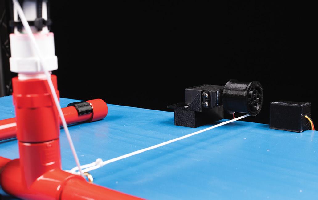
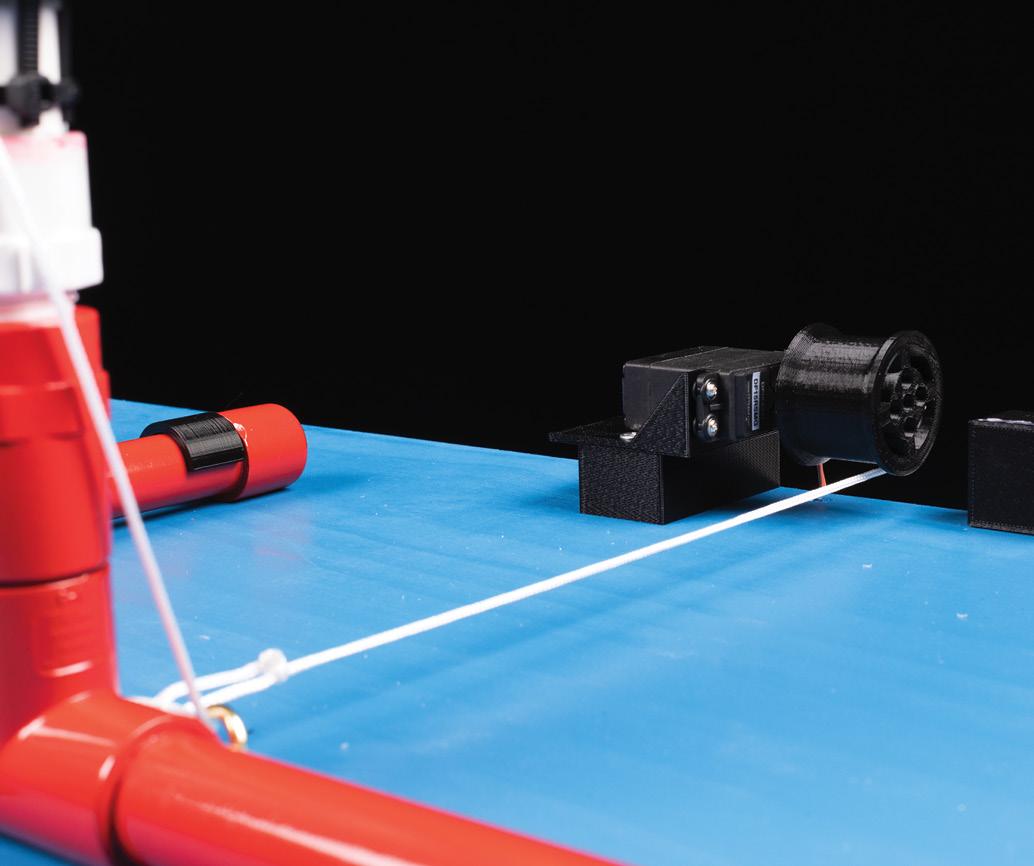
›› easy and neat. If you have the tools, feel free to make the base smaller. On top of the air system is a Clark Cable Tie launcher, which is string-actuated via a servo with a winch drum.
SAFETY SYSTEMS
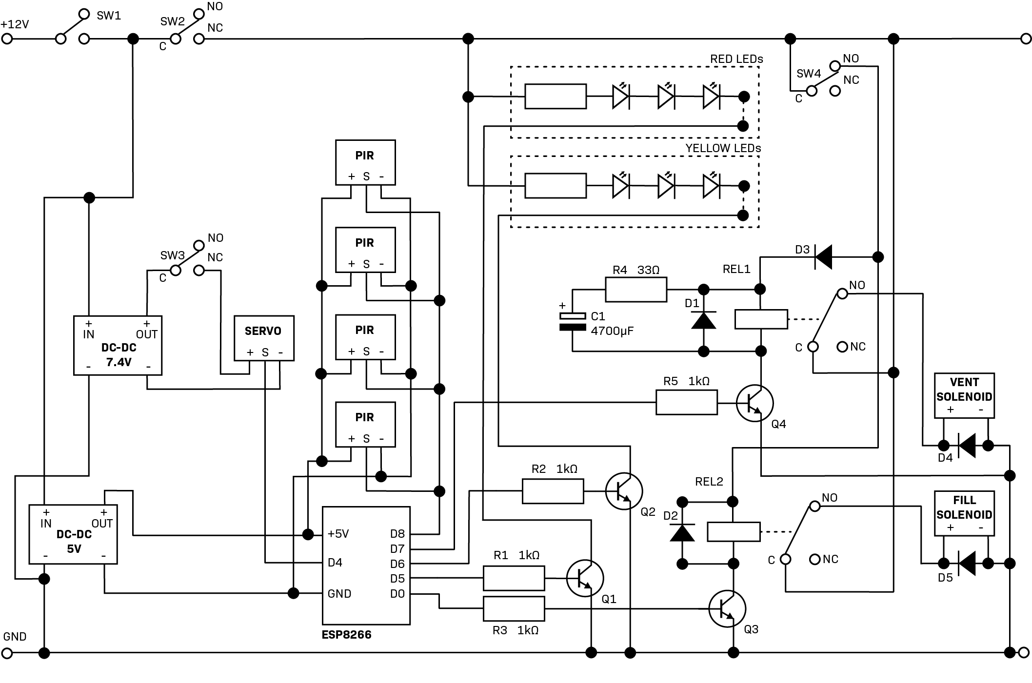
There are multiple layers of safety built into the launcher. Starting with the launcher, battery power to the entire system is controlled by a missile switch. When turned on, this allows power to the ESP8266, which can start up. It also allows power to the common terminals of the relays and the power supply module for the 7.4V servo. Next to these are two limit switches. They are actuated by a long pin, connected to a visible tag. The pin holds the limit switches, which are wired with their normally closed terminals. In other words, the switches are open and unconnected as long as the pin is in. This stops power going to the relay coils, or the servo. In this way, nothing can trigger the solenoid valves or the servo.
The servo in particular can jitter, as many Arduino users are familiar with. Sometimes this is a code issue, while other times it is a cheap servo with poor positional feedback. Either way, it is very undesirable when trying to take up the slack after fitting the collar. Additionally, a powered servo stays in position, while an unpowered one can be rotated. The weakness in this safety system is that it relies on someone remembering or choosing to insert the pin. That's where the designation of one person as a safety supervisor comes in.
Also on the launcher, a limit switch is mounted so that it is only closed when the retention collar is fully in place. This means that the valves cannot be activated unless the rocket is properly seated and secured. Finally, four PIR modules surround the base plate. These are set to a short duration when triggered, and the code will not allow the valves to be powered when there is a signal from the PIRs. This means if anyone approaches the launcher unauthorised, the system will not fire. It will also dump any air that has accumulated.
This is really useful around kids. While the Cheetah is widely said to be the fastest land animal, any parent knows that the fastest living creature is actually a toddler who has been told "Don't go there," or asked "What's in your hands/mouth?". Some teenagers also have a habit of trying to be malicious, particularly at high school events where some guy (let’s face it, it will be a guy) has been dared by his mates to try to launch or even catch the rocket.
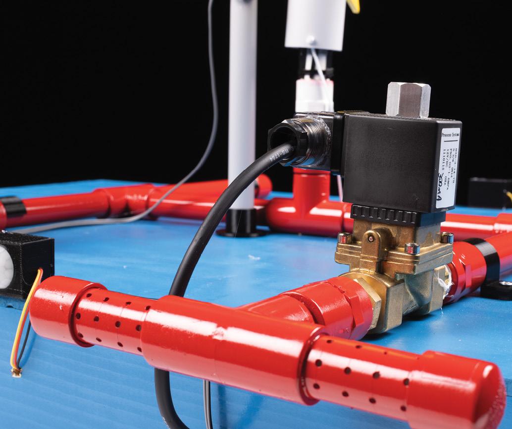
The final onboard safety on the launcher is the valves themselves. One valve controls incoming air, and is a normally closed type. It must be powered to pass air into the system. At the other side is a second valve, and it is a normally open type. It needs power to close. If the PIRs detect movement, both of the relays controlling the air are depowered, and so the normally open valve opens and dumps all the air.
If the power is turned off, via the missile switch or the pin being inserted, any air is dumped. If the collar moves and pulls away from its limit switch but the rocket does not launch, the pressure is dumped. If the wireless signal from the console is lost, the pressure is dumped. There is a slight delay build in via a capacitor and resistor so that the rocket has time to launch in normal operation.
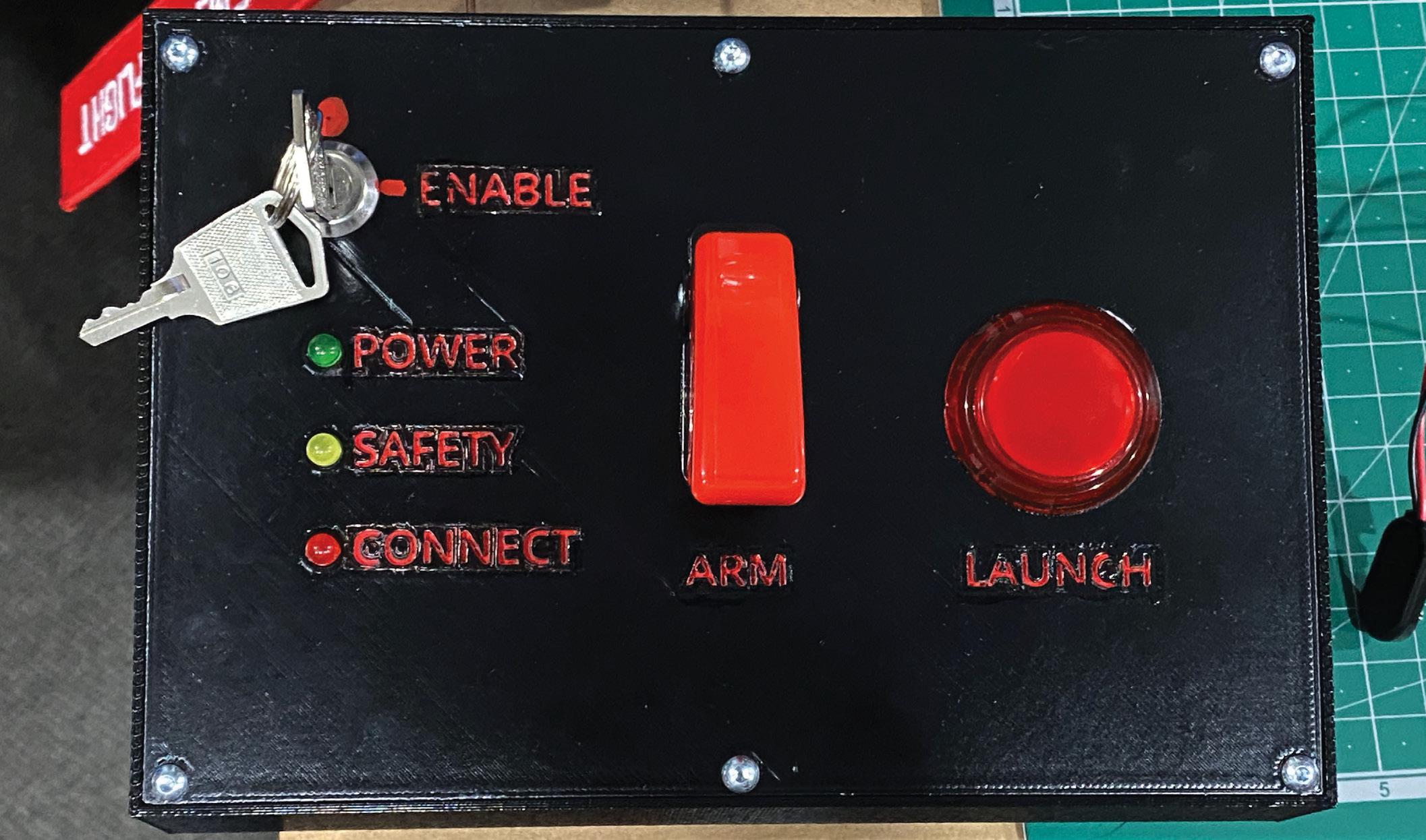
On the console, there are a couple of further safety features. First in line is a key switch to power the whole unit. This allows power to the ESP8266 and the buttons. Secondly, a pin needs to be inserted to hold down a limit switch in order for the 'Arm' and 'Launch' buttons to have 5V fed to them so they can give a high to the relevant pins on the ESP8266.
This pin should be the same one used on the launcher base, so that the console cannot be armed while the launcher is being attended. Finally, the arm switch is a momentary toggle switch protected by a missile cover. This must be held on to charge the launcher with air, and held down until after the fire button has been pressed. If at any time it is released, pressure in the rocket is dumped.
WARNING: MOST OF THESE SAFETY SYSTEMS STILL RELY ON PEOPLE. THEY ARE NOT AUTOMATIC. THEY ARE DESIGNED TO AVOID TRIGGERING OF THE LAUNCHER BY UNFAMILIAR PEOPLE AT THE WRONG TIME, NOT TO GUARD AGAINST CARELESSNESS.
The Build: Base and Frame
While we will break the build down into sections, it is easier to present one bill of materials. It's so big we made it a download via the resources. Don’t go shopping until you’ve read the whole article, however, as some parts may or may not be needed, depending on how you choose to build.
BASE
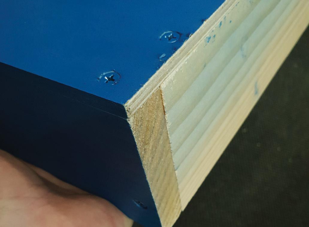
The base is pretty simply built so that almost anyone can have a go. We just cut lengths of 19 x 84mm pine to the lengths of the long sides of the 7 x 600 x 900mm board, and screwed them on from the top using 8G x 20mm screws. One of the shorts sides was measured for the width inside the two side pieces, at the top so that any sloping of the sides wasn’t measured. Then this length was cut and screwed on from the top with 8G x 20mm screws, and also through the sides with 8G x 50mm screws. At the other end, the same applies, however, a gap at least 100mm wide is left for attaching the switch panel later.
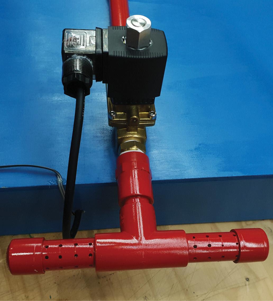
AIR FRAME
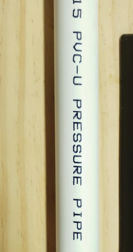
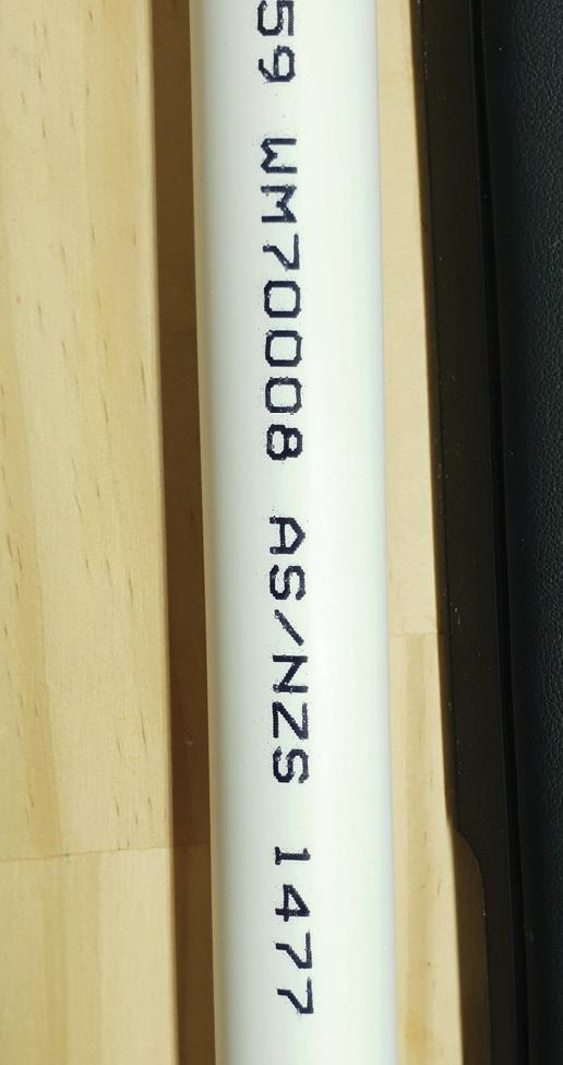
The air frame is made from PVC pressure pipe. Do not use regular conduit, it cannot handle the pressure reliably. There are other types of PVC tube around, too. Make sure you are using PN18 rated pipe. We used 15mm tube, which is the nominal inside diameter and looks, externally, to be very close to 20mm PVC conduit, so be careful! It is generally an off-white, while conduit and non-pressure PVC is usually a grey-shaded white. However, this is not exclusive, so look for the PN18 rating, and the Australian and New Zealand Standard AS/NZS 1477
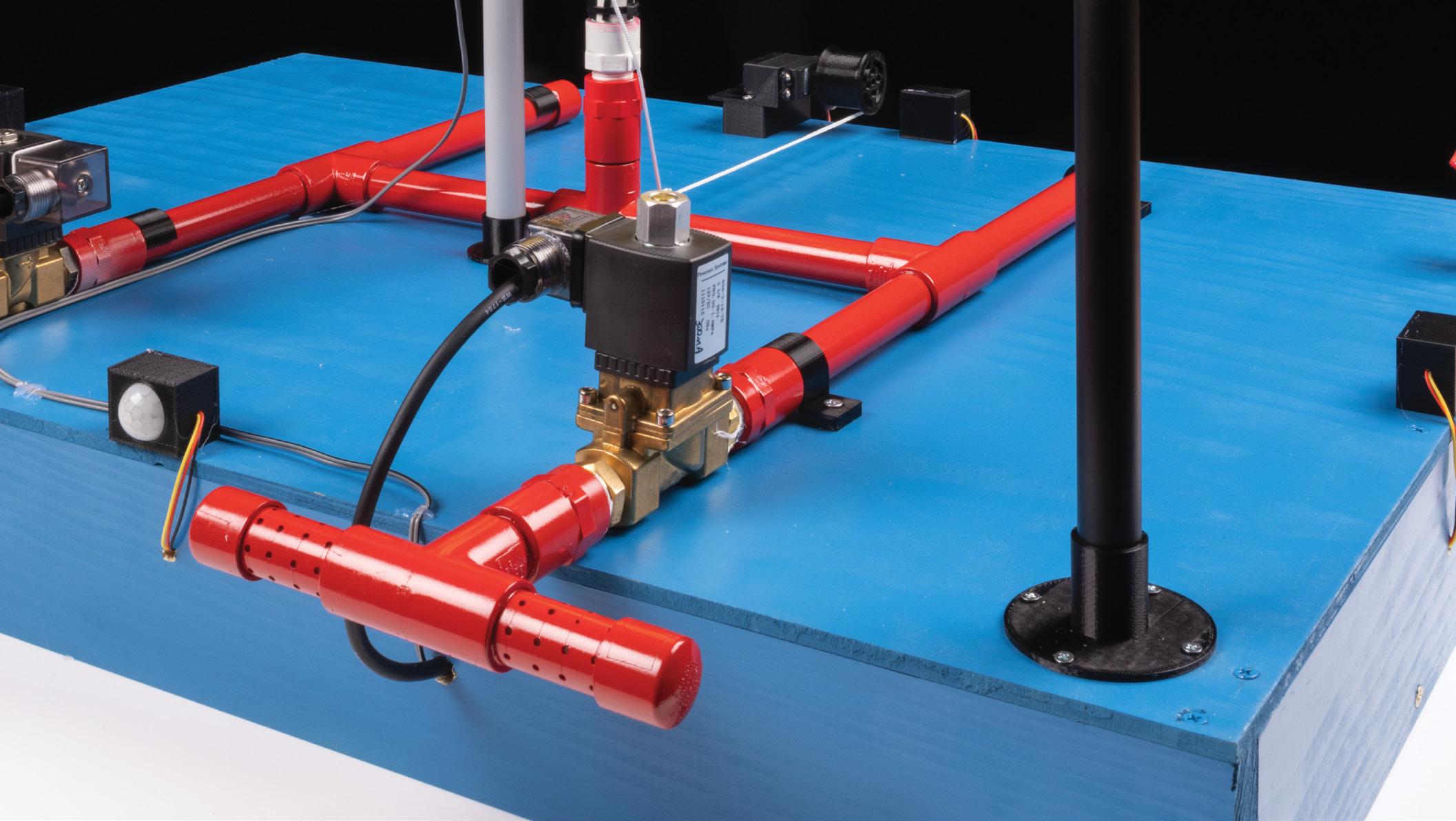
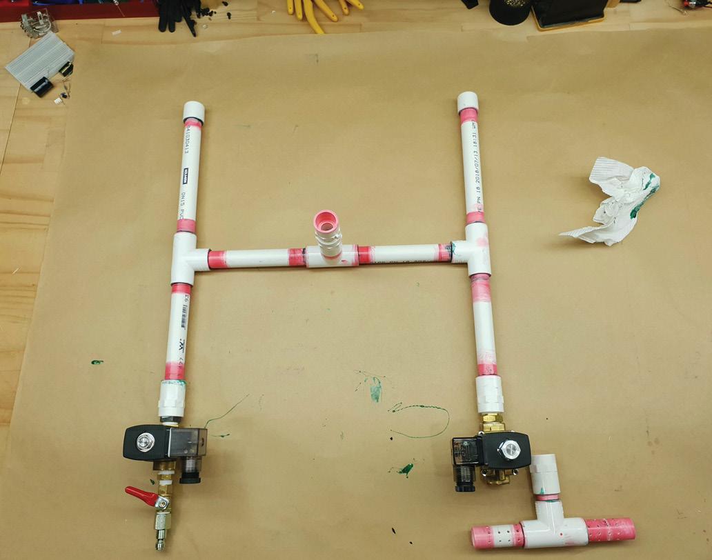
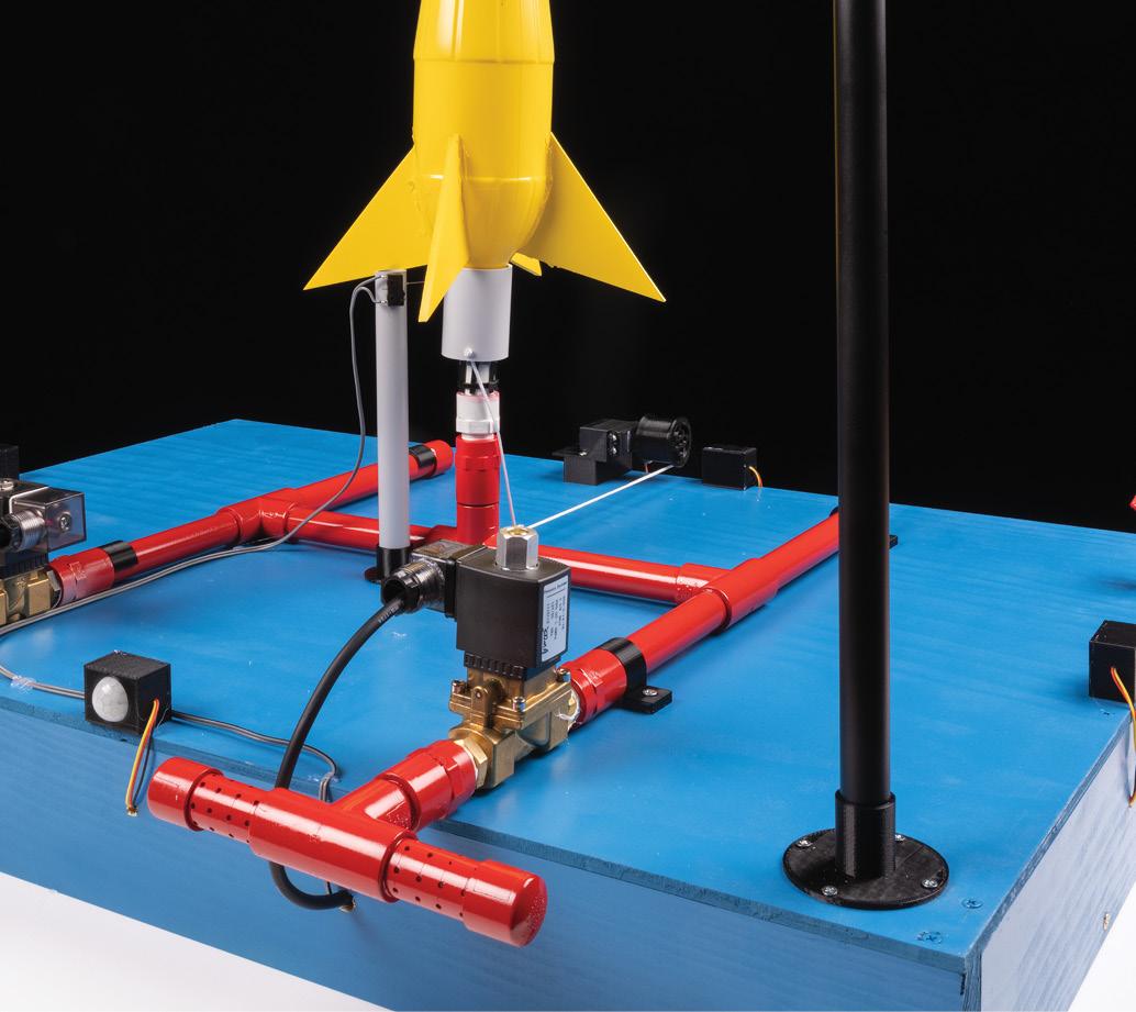
The basic configuration is a H-shape, with a T-junction in the middle, facing upward. This one is a push-fit to threaded fitting, with the 1/2in BSP thread facing upward. The other two Ts are push fit all round. At the ends of the H, one side is fitted with caps, while the other ends in 1/2in BSP threaded adaptors for fitting the solenoid valves.
The size of the H is not critical, and largely depends on the size of your base board. Ours was completely arbitrary. What is important is that it is wide enough to provide stability for the rocket when loaded on top, and when firing.
Cut the desired lengths of PN18 PVC pipe. Do not use conduit cutters! Pressure pipe is brittle compared to conduit, and conduit cutters tend to leave very jagged cuts, or outright shatter the pipe. Use a pipe cutter, which is a rotary device. In the image, conduit cutters are on top, while a pipe cutter is below.

Good pressure joints cannot exist without proper preparation. Red-dyed PVC priming solvent needs to be used to clean the outside of all the pipes where they will join, and the inside of all fittings. Contrary to popular use, this does not just involve smearing some on. It isn’t magic. Use a cloth or paper towel to rub hard enough and long enough that some of the white plastic starts to deposit on the cloth as the solvent dissolves it. Only then can you be sure all contaminants are gone.
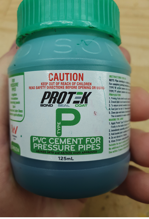
After that, you can glue the joins. Use PVC cement rated for pressure work which is not the blue stuff. Generally, pressure cement is dyed green. Double check the label, as pressure cement is always declared as such. Apply a thin but continuous film of glue to the inside of the fittings and the outside of the pipe. You might find, as we did, that a small paintbrush is far easier than the supplied brush in the lid of the glue.
It may take some practice to get a good bond, because you need enough to make a continuous seal with no gaps, but not so much that it pushes back and runs into the fitting where it shouldn’t. This is more critical in areas where a thread may go later, or a connection you haven’t made yet. If you go back later to bond the other side of, say, a T junction, and find a run of glue has dried there, it won’t come off.
AIR FITTINGS
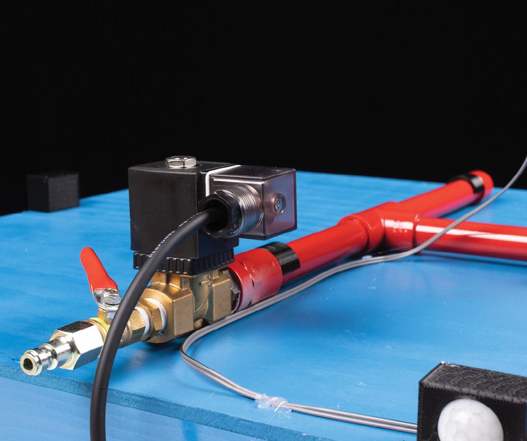
With the PVC done, you can move on to the air fittings. We clumsily bought solenoid valves with a 3/8in BSP thread, while all the PVC pipe fittings are 1/2in BSP and all the air fittings are 1/4in BSP. There is only one extra adapting nipple, however, as there would at least be one whether you bought a 1/2in valve or a 1/4in valve. For the normally closed solenoid that fills the system, we added a 3/8in to 1/2in nipple, to attach to the PVC. If you bought a 1/2in valve, this would screw straight onto a 1/2in BSP male to 15mm push fit adaptor.
On the other side, there is a 3/8in to 1/4in reducing nipple, into a manual valve, which has a 1/4in Ryco style fitting on it. While Nitto fittings are said to be easier, Ryco are strong and still valid. The recently retired Fitter, Turner, and Machinist who advised on this project used nothing else for his entire working career. They’re also what was already on the compressor and hoses we had. The manual valve allows the flow to be reduced. Full pressure will still be reached, just not all at once when the valve opens.
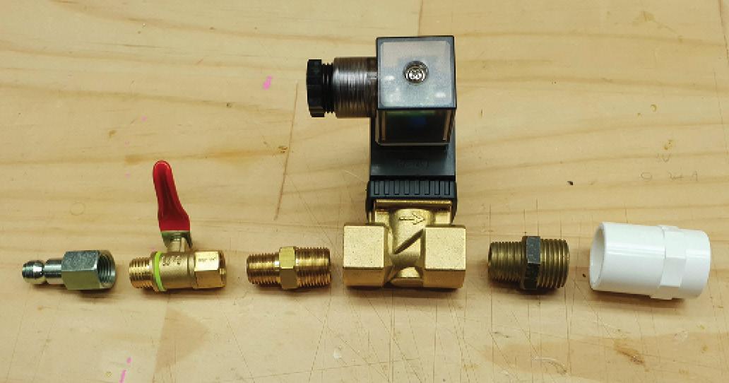
On the normally open solenoid valve, we have 3/8in to 1/2in adaptor nipples again. If we bought a 1/2in valve, we could have used 1/2in to 15mm push fit adaptors of the opposite gender to the ones you see in the picture. On the outward side of the valve, we have a bit more PVC. It’s a T-shaped fitting with a bunch of holes drilled, so that if full pressure is dumped suddenly, no debris can be thrown or jets of air directed anywhere.
It dissipates out the array of holes. This is not totally necessary in hindsight, because we later added the water stopper at the top of the launch tube, which slows the air flow. However, not everyone will fit this, and if the air path from bottle to vent is 1/2" or 15mm pipe all the way, it can be unsafe.
Two very important points need to be noted here. Thread seal tape should be used, and has a direction. Make sure you lay it so that when rotating the thread, the end of the tape is dragging behind. If you lay the tape the other way, the tape end faces the direction of rotation, and will be curled and bunched up.
More critically, there are two types of BSP thread. Water pipe BSP fittings (which pressure PVC usually is) are straight. However, air fittings and some others are often BSP-T, with T for Taper. The thread body tapers in diameter. That means that after hand-tightening, not much rotation is needed to get a good seal. If over-tightened, BSP-T threads will split PVC, and can even split metal connections if they are too thin-walled, or brittle cast aluminium.
With the valves attached to
the air frame, the entire assembly can be mounted to the base plate. When we were buying, our hardware store was out of saddles (and many other things. Thanks, Covid!) so we 3D printed some. We have included these files but if you have saddles, those are fine.
| Parts Required: | ID | Jaycar | ||
|---|---|---|---|---|
| 1 x Red LED* (Connect indicator) | C: LED3 | ZD1690 | ||
| 1 x Green LED* (Power indicator) | C: LED1 | ZD0170 | ||
| 1 x Yellow LED* (Safety indicator) | C: LED2 | ZD0160 | ||
| 12 x High-Brightness Red LEDs* | Stack LED1-12 | ZD0154 | ||
| 12 x High-Brightness Yellow LEDs* | Stack LED1-12 | ZD0162 | ||
| 1 x Superflux square Red LED | C: LED4 | - | ||
| 1 x SPST 12mm Toggle Switch | L: SW1 | ST0579 | ||
| 1 x SPST Momentary 12mm Toggle Switch | C: SW3 | ST0577 | ||
| 1 x 10A SPDT Limit Switch | L: SW2 | SM1040 | ||
| 2 x Missle Switch Covers | C: 1 L: 1 | ST0578 | ||
| 3 x 5A SPDT Limit Switches | C: S2 L: SW3,SW4 | SM1038 | ||
| 1 x Mini Barrel Key Switch (Enable switch) | C: S1 | SM1027 | ||
| 1 x Red Illuminated Arcade Switch (Launch switch) | C: S4 | SP0662 | ||
| 2 x 5A SPST or SPDT Relays | L: REL1, REL2 | SY4062 | ||
| 1 x 33Ω Resistor* | L: R4 | RR0536 | ||
| 1 x 100Ω Resistors* | C: R8 | RR0548 | ||
| 3 x 150Ω Resistor* | C: R1, R2, R3 | RR0552 | ||
| 8 x 300Ω Resistors* | Stack R1-4 | RR0559 | ||
| 6 x 1kΩ Resistors* | C: R4, R7 L: R1, R2, R3, R5 | RR0572 | ||
| 2 x 10kΩ Resistors* | C: R5, R6 | RR0596 | ||
| 2 x 100nF Ceramic Capacitors* | C: C1, C2 | RM7125 | ||
| 1 x 4700µF 16V capacitor | L: C1 | RE6243 | ||
| 5 x 1N4004 Diodes* | L: D1-D5 | ZR1004 | ||
| 6 x BC337 NPN Transistors* | C: Q1, Q2 | L: Q1-Q4 | ZT2115 | ||
| 2 x ESP8266 Modules | C: 1 L: 1 | XC3802 | ||
| 2 x DC-DC Converter modules | L: 1 | XC4514 | ||
| 1 x LiPo Rider module | C: 1 | - | ||
| 4 x PIR Module | L: 1 | XC4444 | ||
| 1 x 26650 Battery | C: 1 | SB2319 | ||
| 1 x 20kg Servo | L: 1 | - | ||
| 2 x Half-size Solder Breadboards | C: 1 L: 1 | HP9570 | ||
| 1 x Small section Veroboard | L: 1 | HP9540 | ||
| PCB Pins | - | HP1250 | ||
| Light Duty Hookup Wire | - | WH3010 | ||
| Light Duty Hookup Wire | - | WH3011 | ||
| Medium Duty Hookup Wire | - | WH3040 | ||
| Medium Duty Hookup Wire | - | WH3041 | ||
| 7.2Ah SLA Battery | L: 1 | SB2486 | ||
| 1 x Normally Open Solenoid Valve | L: 1 | - | ||
| 1 x Normally Closed Solenoid Valve | L: 1 | - | ||
| Packet of Wire Links | - | PB8850 |
ID: C = Console, L = Launcher
*Quantity required, may be sold in packs. ^Similar to one used, however, some modifications may be required. Additionally, Timber, PVC Pressure pipe and fittings are needed, but vary by user design. See text.
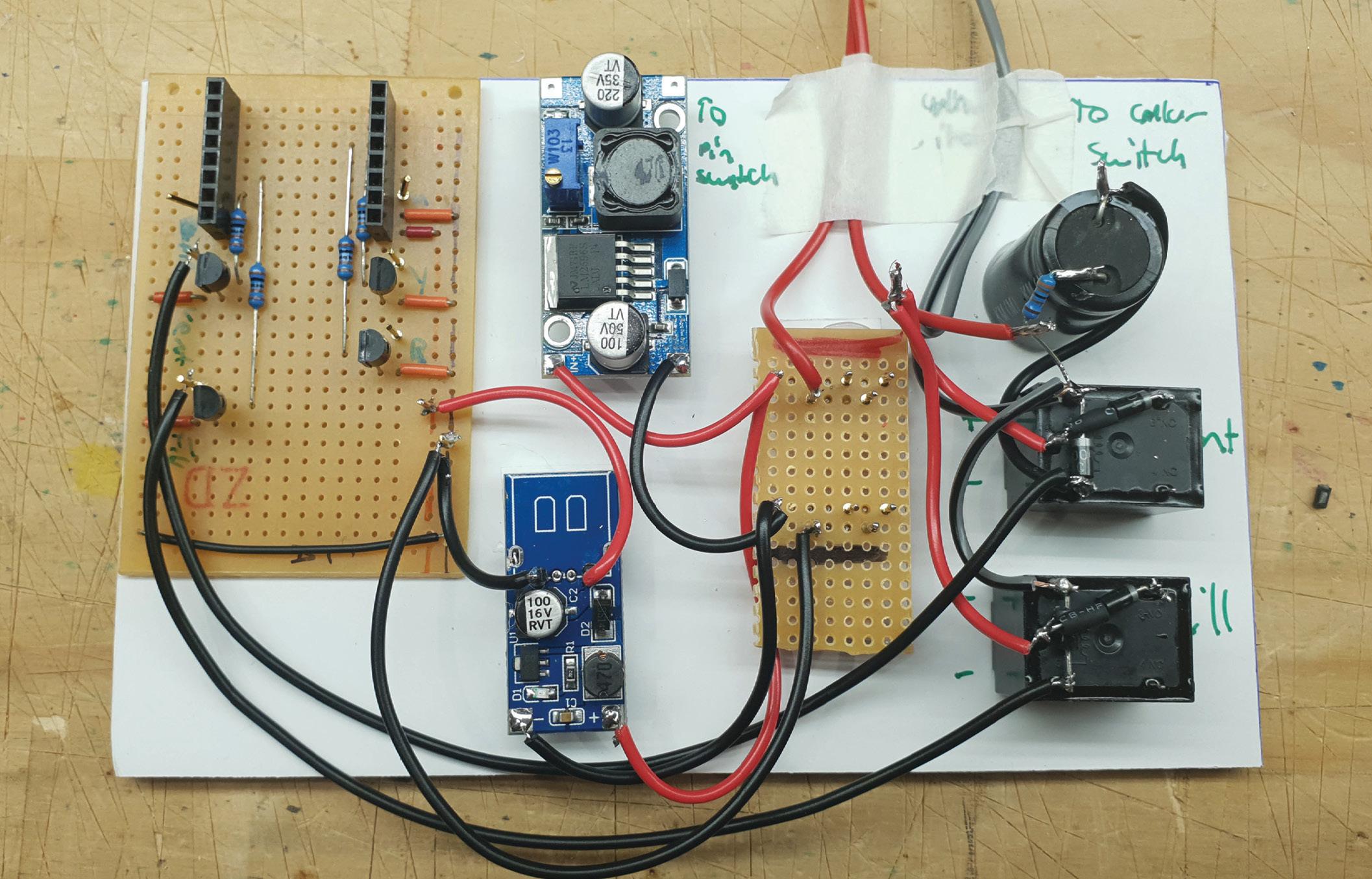
The Build: Launcher Electronics
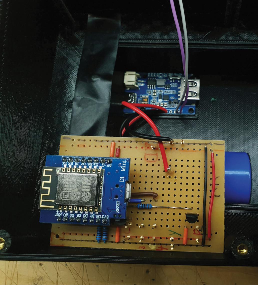
Building the electronics for the launcher involves a pile of off-board wiring, which is no fun, and a limited circuit board to hold the ESP8266 and the transistor drivers. Two of these transistor drivers control the solenoid relays, while two control the stack light.
All are NPN drivers because the relays and stack light are 12V, while the ESP8266 is 5V. That’s still plenty to activate the base of a BC337, and because the emitters are connected straight to ground, and both the base and collector (load) current go there, there is no voltage contamination from the 12V to the 5V. That wouldn’t be the case if we used high-side PNP switches.
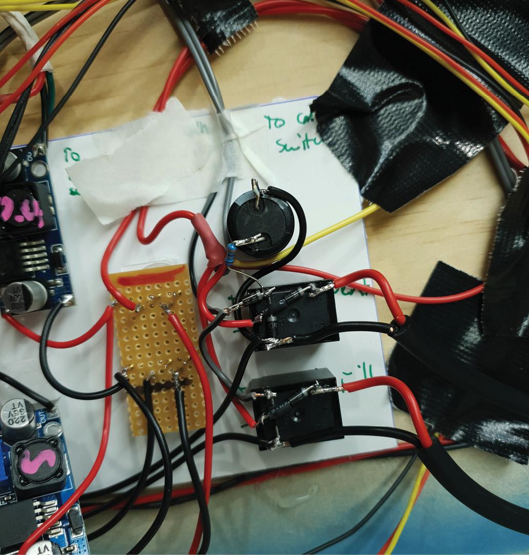
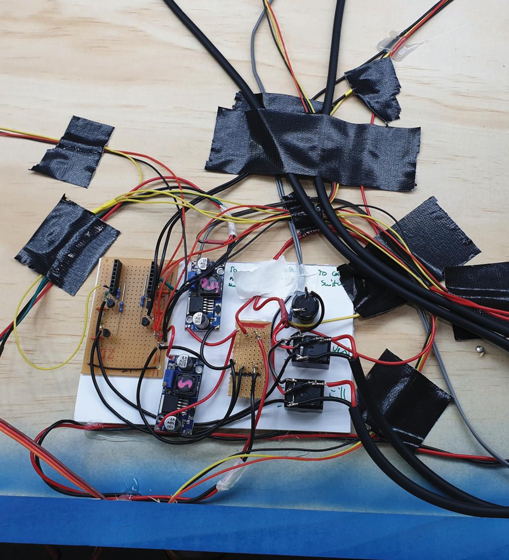
The photograph shows the PCB without the ESP8266 installed, as it covers some of the details. What you can see is the two power modules, two relays, a 12V distribution board made from vero and PCB pins, and the 4700µF capacitor and 300Ω resistor for the dump valve relay. These haven’t been discussed yet. They are there to ensure that the dump valve stays closed after the collar on the launch mechanism moves and opens the limit switch, as it takes a moment for the rocket to break its seal and move. Dumping the air straight away would be a problem.
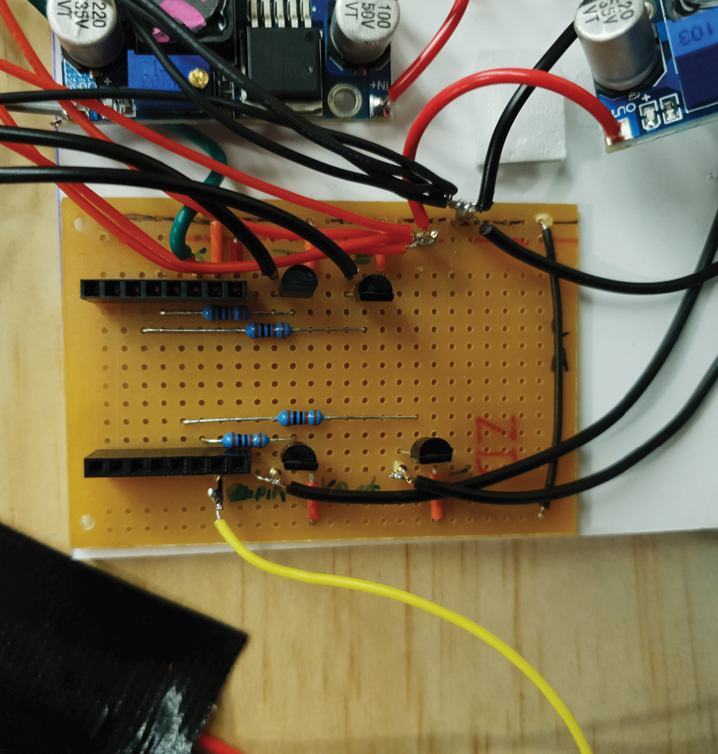
Unfortunately, the photographs are not wonderful, because there are necessarily wires everywhere, but hopefully, you can see enough of what’s going on to work it out in conjunction with the schematic. You can also see flyleads left for the limit switches. They are labelled on the board. Two are called ‘pin switch’, which are the servo limit switch and master 12V limit switch that are used in conjunction with the safety pin. The other is the collar limit switch. The 7.4V PSU is an adjustable unit, while the 5V PSU is an old USB converter we had. In the parts list, we list two adjustables because we have no idea where we got this 12V to USB converter from, but we think it was from an old in-car project that never happened.
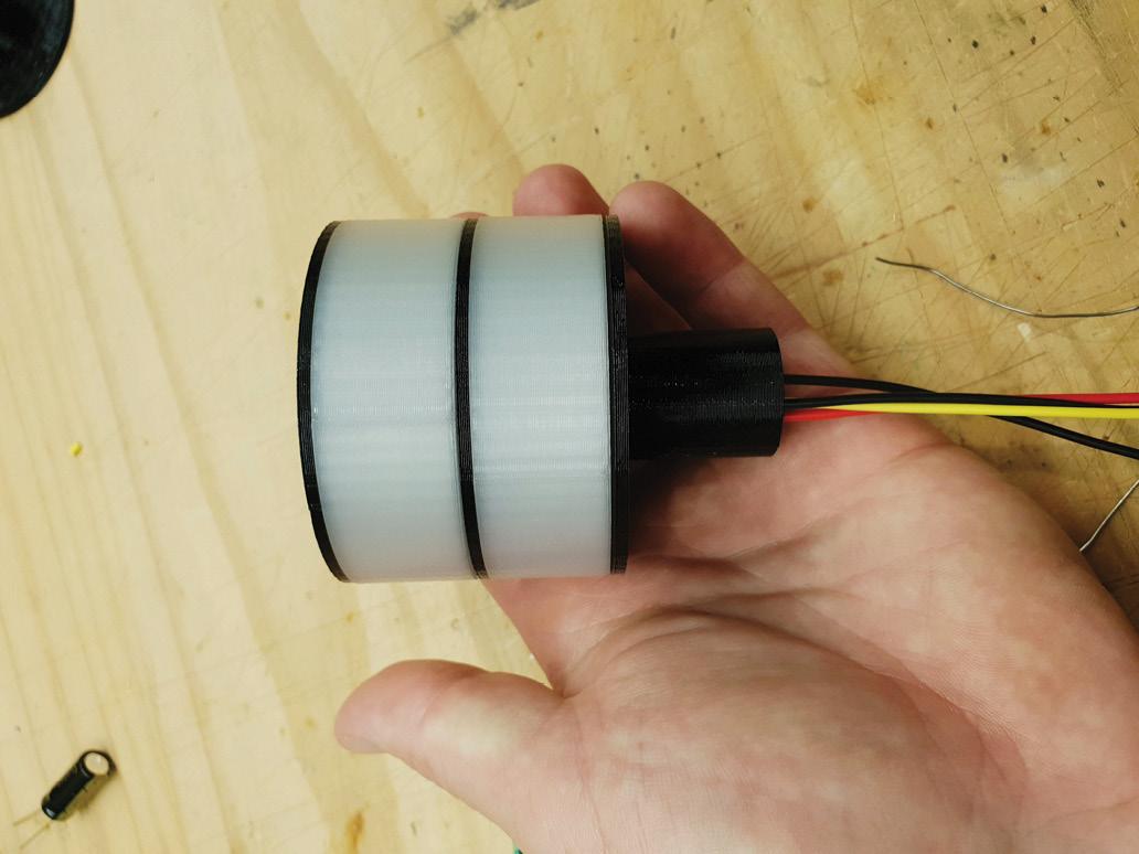
STACK LIGHT
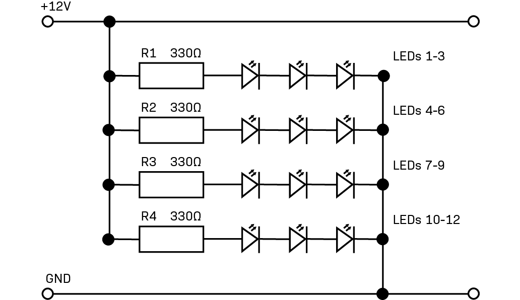
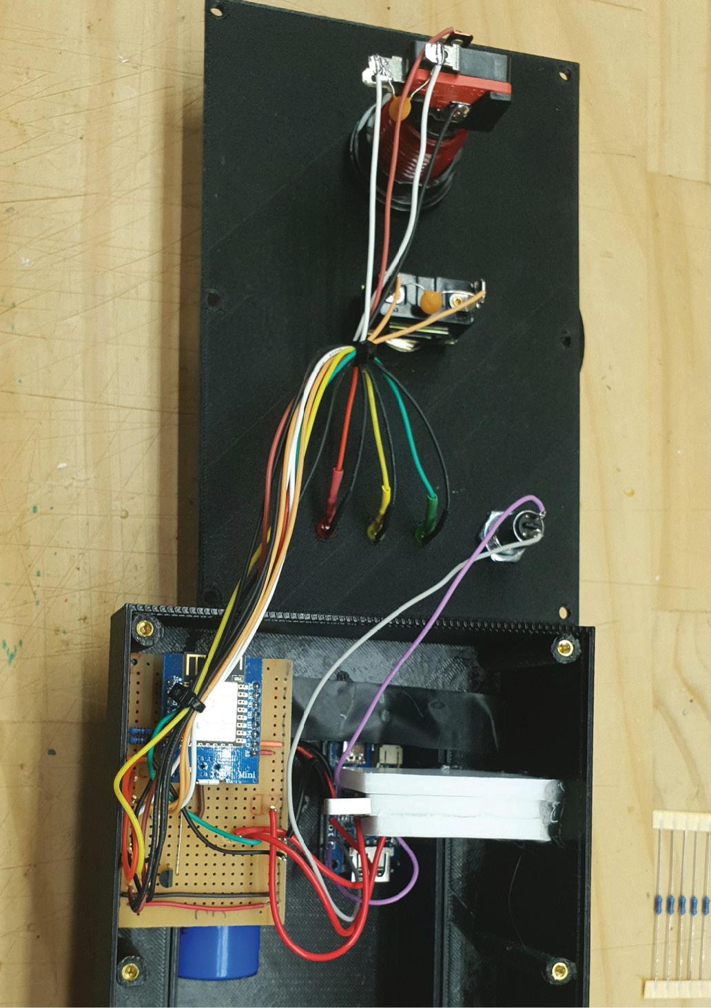
We made our own 3D printed stack light to indicate at a distance the status of the launcher. This consists of twelve LEDs for each light, arranged as four parallel groups of three LEDs and one resistor in series. The LEDs are glued into the 3D printed diffuser element, then have their legs cut and soldered appropriately. All connections are brought to a common power and ground wire for the whole light.
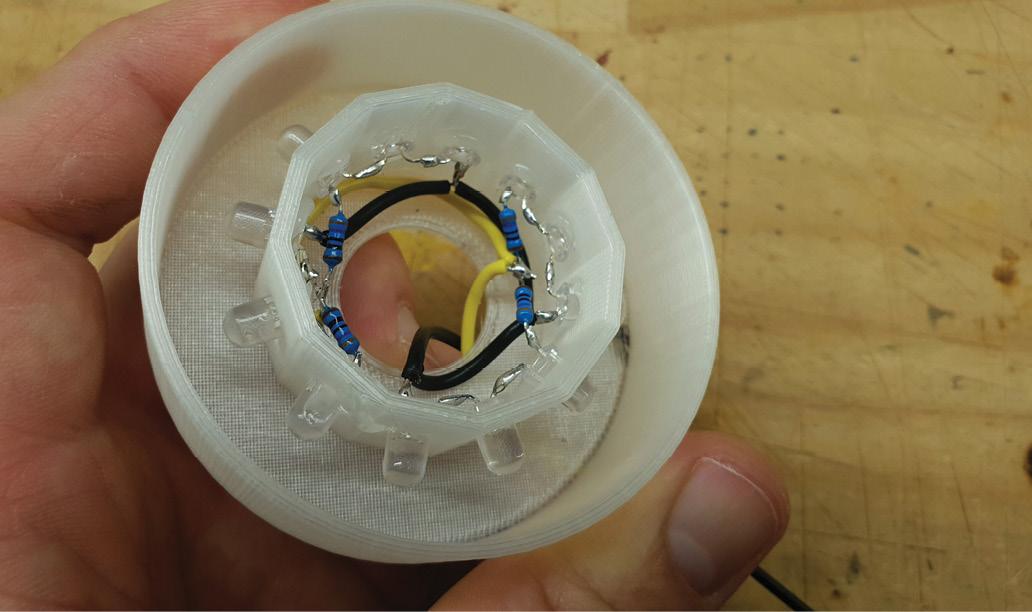
There are two lights, one red and one yellow. In our case, the chosen LEDs had almost the same forward voltage and current, so we used the same resistors. If using a stack light for another purpose where you may want green or blue, these resistors would change. ››
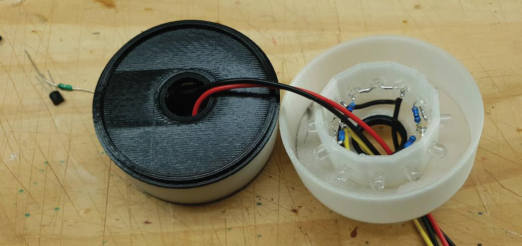
›› After two lights are made, they are joined. The lights are identical, and there are middle layers to stop light bleeding. Layers are joined by inserts, and there is a mounting base as well. The same element is printed twice. One screws to the baseboard, while one mounts on the top of the post (which is just 20mm electrical conduit) and uses another joiner insert to attach to the stack.
The Build: Console Electronics
The console wiring and building are best conducted together. There is a deeper 3D printed section which bolts on with M3 screws, in order to give depth for the arcade switch, battery, and missile switch, while leaving a thinner section to hand-hold the case. We designed this with flanges with a triangular underside, so they can be printed without supports. However, this makes bolting a little awkward as the nuts do not touch a flat surface.
It also helps to install the LEDs and switches before any other wiring. The missile switch goes straight in, but the arcade switch needs modifying, which we’ll describe next. The key switch can also go straight in. Be careful of the order of the LEDs in terms of their colour. Also, we filled in the engraved lettering on the front of the panel with red paint marker, and wiped off the excess. It still leaves marks on the surface, so we had to go over some with a black paint marker.
The arcade switch comes with a 12V LED fitted. More accurately, it comes with a 4.8mm low-dome wide-angle LED fitted with a resistor for 12V, all mounted in a wedge base. Because we had to remove the LED to change the resistor for 5V, we scrapped the lot and installed a flat red superflux-style LED with a wide angle and a higher brightness. First, we bent in the pins of the LED, and cut off two of the four. The resistor is soldered to one, while a piece of tinned copper wire is soldered to the other.
Then, the assembly is carefully inserted into the wedge housing and the resistor leg and copper wire are wrapped around the appropriate place on the base. The LED is now ready to be inserted into the wedge socket in the switch body.
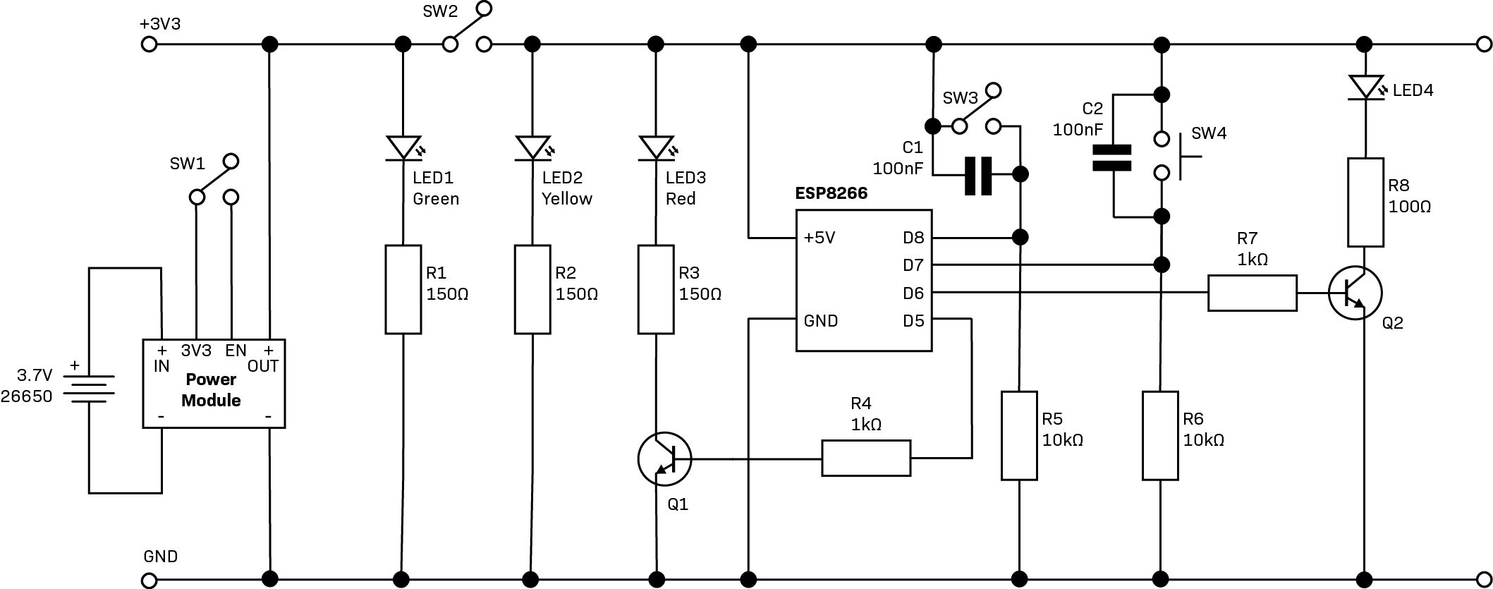
The console is powered by a 26650 battery and a LiPo Rider DC-DC converter and battery charger combination. This means we cannot use a switch between the battery and DC-DC converter, otherwise the battery cannot charge. Instead, connecting the 3.3V output on the LiPo rider to the EN terminal activates the 5V output. We did this via the key switch. This does mean a quiescent current drain.
If you look closely, you can see a bunch of PCB pins. Under the ESP8266 are some wire links. The PCB pins with marker labels ‘3’ and ‘4’ correspond to switches S3 and S4. You can see one side of the pair of pins is in the 5V rail, while the other connects to the blue and brown wire links. These go to ESP8266 pins D8 and D7, where you can see the 10kΩ resistors for stopping floating. The capacitors for debouncing shown in the schematic are soldered directly to the switches.
Hiding under the edge of the ESP8266 is one BC337 transistor labelled ‘C’. The base connects to ESP8266 pin D5 via a 1kΩ resistor hidden under the board, while the emitter is connected to ground. The pins in the supply rail and the transistor’s collector go to the ‘Connected’ panel LED, hence the ‘C’ label in marker. A green ‘Y’ shows where the ‘Safety’ LED connects, just across the supply rails which are only active when the safety switch is activated. At the lower end, another BC337 fed by a 1kΩ resistor from pin D6 is connected to the LED from the arcade switch.
One more thing to note: The power from the DC-DC converter is wired to a pin on its own on the PCB, while the PCB pin in the supply rail has no wire. This is for later, because the limit switch which takes the safety pin will be wired to this pin, and the supply rail so that power is only to the ESP8266 when the safety pin is installed. The green LED is wired to this isolated pin, too, so it lights as soon as the key switch is turned, enabling the 5V output of the LiPo Rider.
We wired the console with silicone hookup wire but any hookup wire will do. Most of what is wired we have already described. You can see a foam-core assembly with the limit switch protruding from it. This is where the safety pin ends up when inserted through the side of the case. The wires from the PCB go to the COM and NO terminals of this limit switch. The rest is fairly self-explanatory. Just take care with the LED polarity for the arcade switch. Heated inserts were used in conjunction with M3 bolts to close the lid of the console.
LAUNCHER WIRING
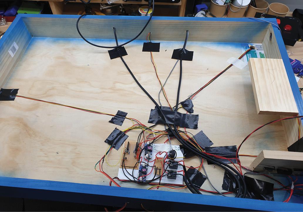
Earlier, we built the main circuit and left flyleads for some connections. The underside of the launcher wiring looks crazy because it is. This could be made neater but we were running out of sanity and it needed far more time that the result would justify.. There is a limit to how much you can achieve. We added two pieces of timber. One is screwed horizontally near the base and has a piece of foam core glued to it, and is a snug fit for the battery. The other mounts vertically next to that and is for the limit switches. This happens to be a good fit for the location of the opening for the safety pin.
These limit switches were wired with the flyleads left from earlier. The 12V wire carries the full solenoid current and is a 10A limit switch wired with 7.5A hookup wire, seen leaving the electronics in the earlier photos. The 7.4V servo flylead carries far less current and is wired to a 5A limit switch with speaker wire. These were glued on with hot melt glue while the pin is installed so that the switches are comfortably depressed but not tight.
We also glued on the enclosures that mount the PIRs in them. Adjust the sensitivity to the middle and the delay to the minimum. Small hookup wire was soldered to the pins on the PIRs, then they were mounted in the boxes and the backs glued on. A hole was drilled in the timber frame and the wiring sent inside. We drilled more holes for the solenoid valve wiring.
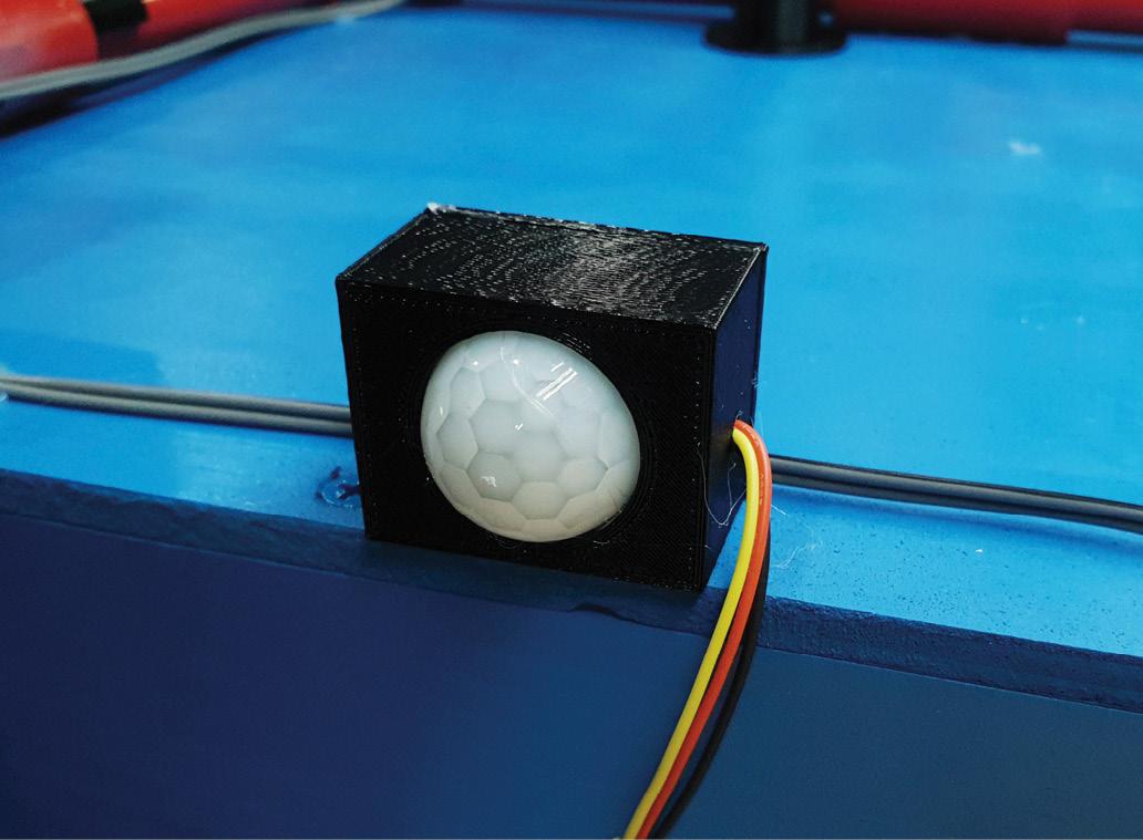
The valves themselves are 12VDC but the connections are not polarised. Each unit should come with wiring instructions. After using the screw terminals on the connectors to attach round power cable, these were fed inside the frame.
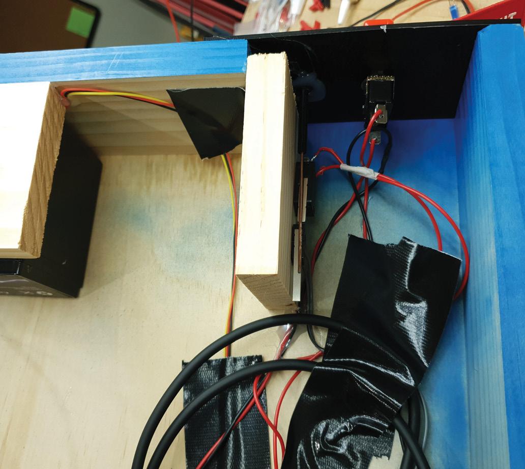
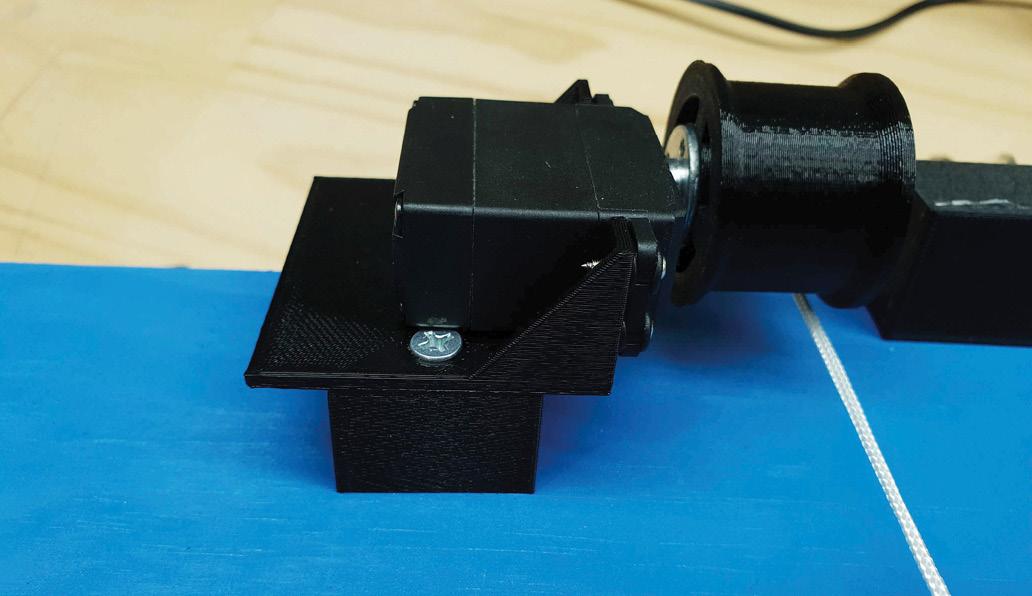
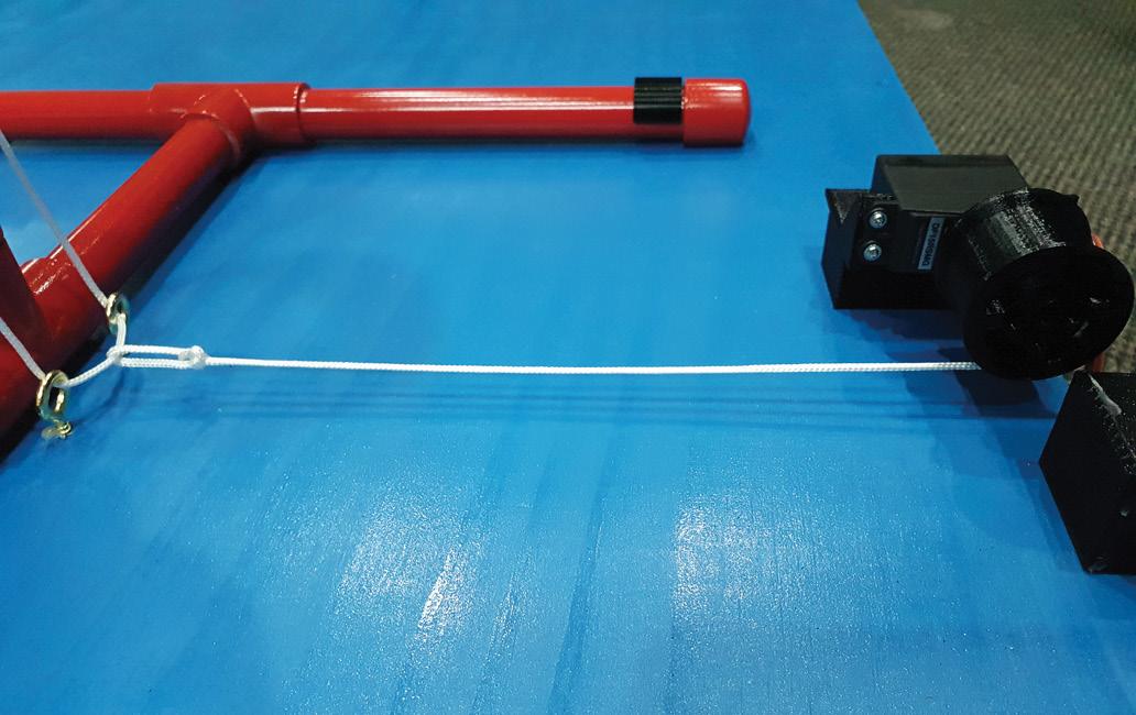
On the opposite side, the servo mounts on a bracket with a separate spacer. The bracket and spacer both mount with the same pair of 8G x 35mm screws. Then, the servo was mounted with its supplied self-tapping screws before the winch drum was installed. The winch drum mounts to a hub that came with the servo, again using the included hardware.
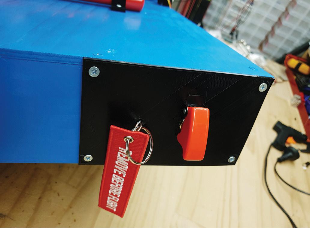
On the side of the frame, the missile switch plate was attached with 8G x 20mm screws. On the back, a guide was glued for the safety pin.
Now the serious wiring can begin. The battery was connected with 7.5A hookup wire, in red and black which we twisted together. The wires were first run to the missile switch, where the red wire was cut and soldered to the SPST switch. Then the wires were routed to the distribution board made out of vero. The fly leads for the limit switches were soldered on too, now that the hot melt glue had properly cooled. The solenoid valves had their ground wires soldered to the ground side of the relays, while the positives went to the NO pins. The 12V for them is supplied from the COM terminals when the relays close, which were wired to the limit switch fly leads earlier on.
The wires from all four PIRs were taken together and the red, yellow, and black wires bundled before being stripped, soldered together and attached. The red and back wires go to the ESP8266 PCB, where they attach to the power rails there. The yellow wires go around to pin 8.
The servo fly leads were also attached now. The plug was cut off and the relevant wires soldered on. The connections to the limit switch and power were done in the earlier step, which was a blessing because the work environment on the floor with the unit on its side was not great.
The only electrical connection remaining now is the collar limit switch.
RELEASE SYSTEM AND FINAL TOUCHES
Earlier on when we built the air frame, it ended at a threaded connector. This allows the fitting of different launch tubes. While we intend to use the same system, being able to have multiple attempts at making it is useful. We are using the Clark Cable Tie system. In many online videos, these use a PVC pipe joiner as a collar.
We could not find one the right size, but found that 40mm non-pressure (i.e., sewer/drain pipe like you find under a sink) is the perfect size. We bought a 1m length of this and cut a section off with a drop saw. It’s too big for the pipe cutter we have, and the conduit cutters. If you don’t have a drop saw, you’ll need a hack saw and a lot of care.
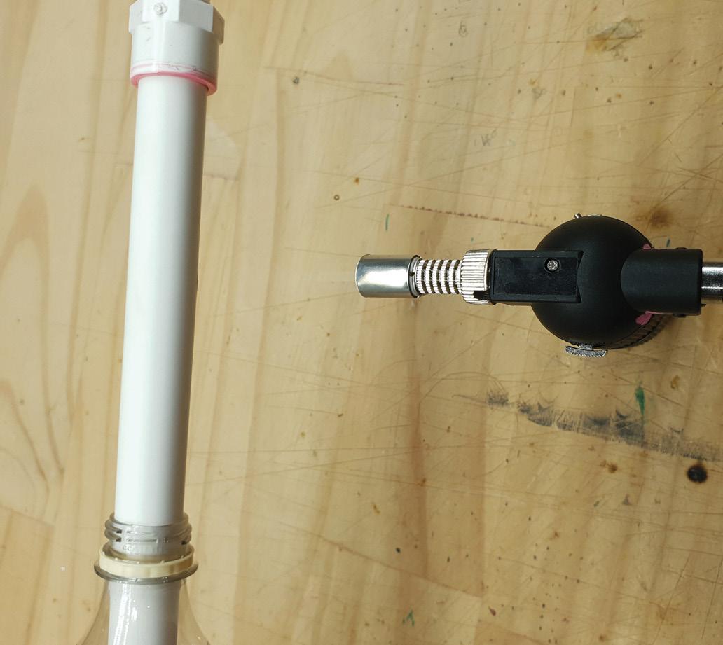
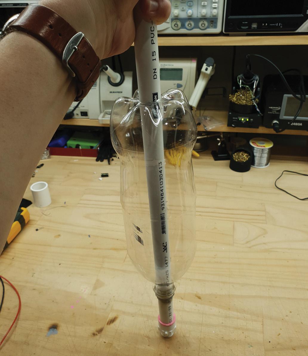
Start by sliding a length of 15mm pressure PVC pipe into the threaded to push fit adaptor. Cut a hole in the end of a soft-drink bottle. Heat an area of the pipe around 100mm from the adaptor end, using a gas torch and turning the pipe so the whole ring gets heated.
When it is soft, slide the bottle down so the neck is over the heated section (this is why we cut a hole in the end) and push both the adapter end and the end sticking out of the bottle. Try to keep the sections straight and aligned. This deforms the tube so that it swells and makes a tight seal. ››
Some videos suggest an o-ring as a seal, and demonstrate methods for making the launcher for it. This involves cutting the pipe, finding a well-fitting inner section, and gluing them down tight on the o-ring but not so tight it cannot be removed or deform. We couldn’t find the right sized o-ring at any retailer. They come from engineering suppliers in orderable sizes, but we were at the mercy of what the hardware store happened to stock. We also couldn’t find the right size inner tube. Both deformed tube and o-ring tubes work with the cable tie launcher.
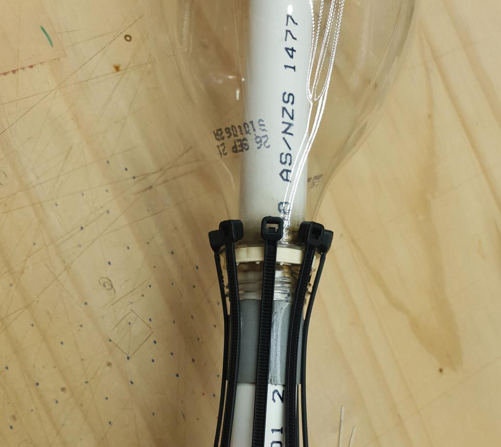
Next, with the bottle still on the right part of the tube, wrap the tube between the bottle and adapter with double sided foam tape. The outdoor/automotive type works best. Lay eight cable ties equally spaced around the tube, with their heads sitting firmly down on the neck of the bottle. Note the orientation that makes this possible, with the ribbed side facing outward.
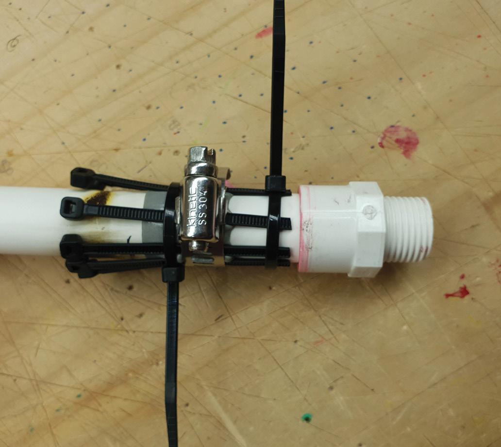
Use a hose clamp to squeeze the cable ties and tape firmly. When they have compressed as much as practical, wrap two more cable ties around, and pull them tight with pliers. Now the hose clamp has to be removed, because the collar will not go over it. Trim the ends of the cable ties. Ideally, this would be covered in epoxy over the not-taped sections, but we haven’t yet for photographic reasons. The tube can now be cut with a pipe cutter, about two thirds of the way up a regular soft drink bottle.
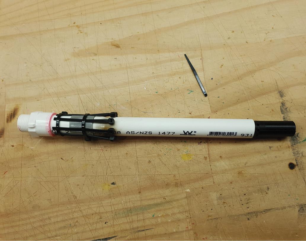
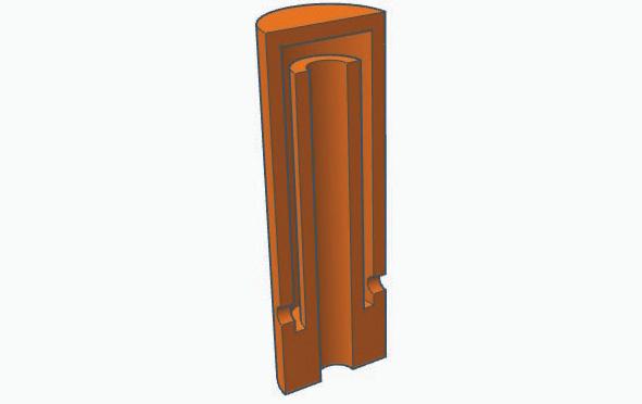
On the top of the tube, you will note a black 3D printed section. This is a way of keeping water from getting into the air system as the rockets are loaded. The lower half is a disc the diameter of the inside of the pipe, with a smaller tube extending upward. Over this is glued a hollow cylinder with one end closed, and holes around the outside of the other end. This cylinder is 5mm longer than the tube of the lower half, and has a void between the tube and the walls of the cylinder. When the tube is glued over the lower part, the result is that air can pass up the tube, down the void, and out the holes. Water, however, can flow in the holes but has to flow all the way up the void to get into the air system.
Because the bottle is pushed on reasonably quickly, this section is never submerged long enough for the water to make it all the way up the void. When the bottle is in position, the water drains back through the holes. Remember, the air system is not closed because of the normally open vent valve. If it was, water would never make it up the void because of air pressure. With no cap at all, water pours down the pipe and simply displaces air.
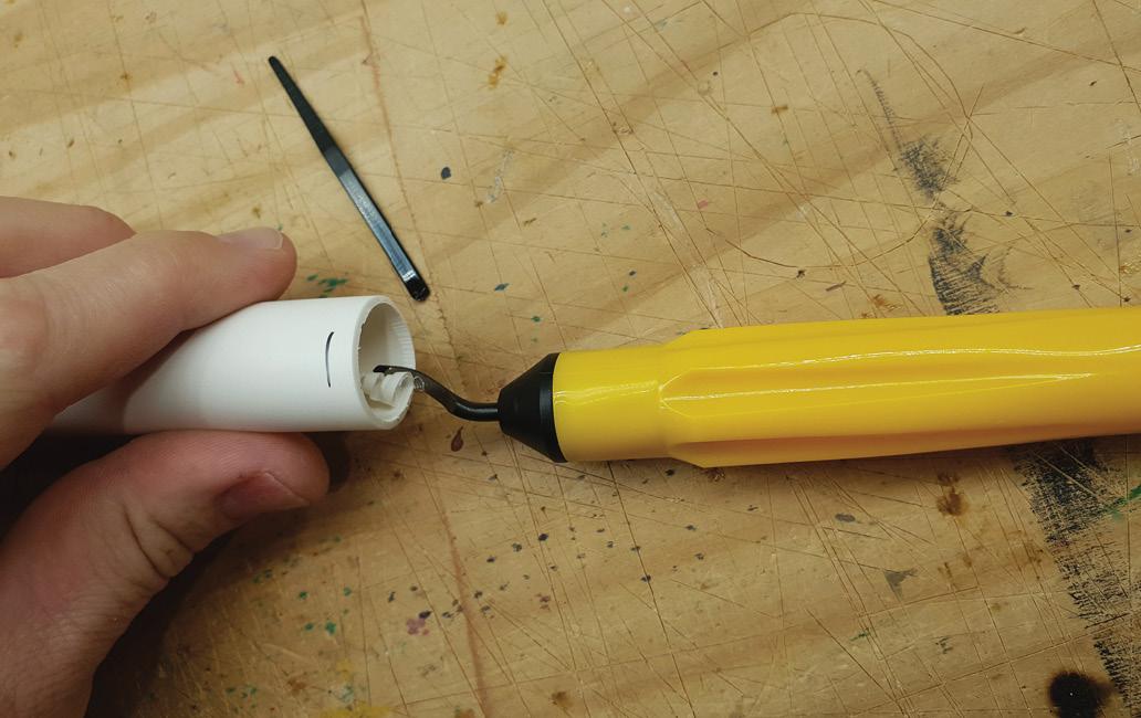
Cutting tubes with a roller type pipe cutter leaves a rolled inward edge. To fit the tube a deburring tool had to be used to remove this.
Little remained at this point. Two eyelets are added under the launch tube. The collar made from 40mm PVC pipe had two holes drilled in it, then it was slid over the launch tube. A loop of string long enough to pass through both eyelets from the collar was cut from a roll of Venetian blind cord. This polymer string ties well but has no stretch. A new bottle, without a hole, was installed. The collar was slid to the home position, and the cord tied so that the ends protruded from the collar, and the loop passed through the eyelets.
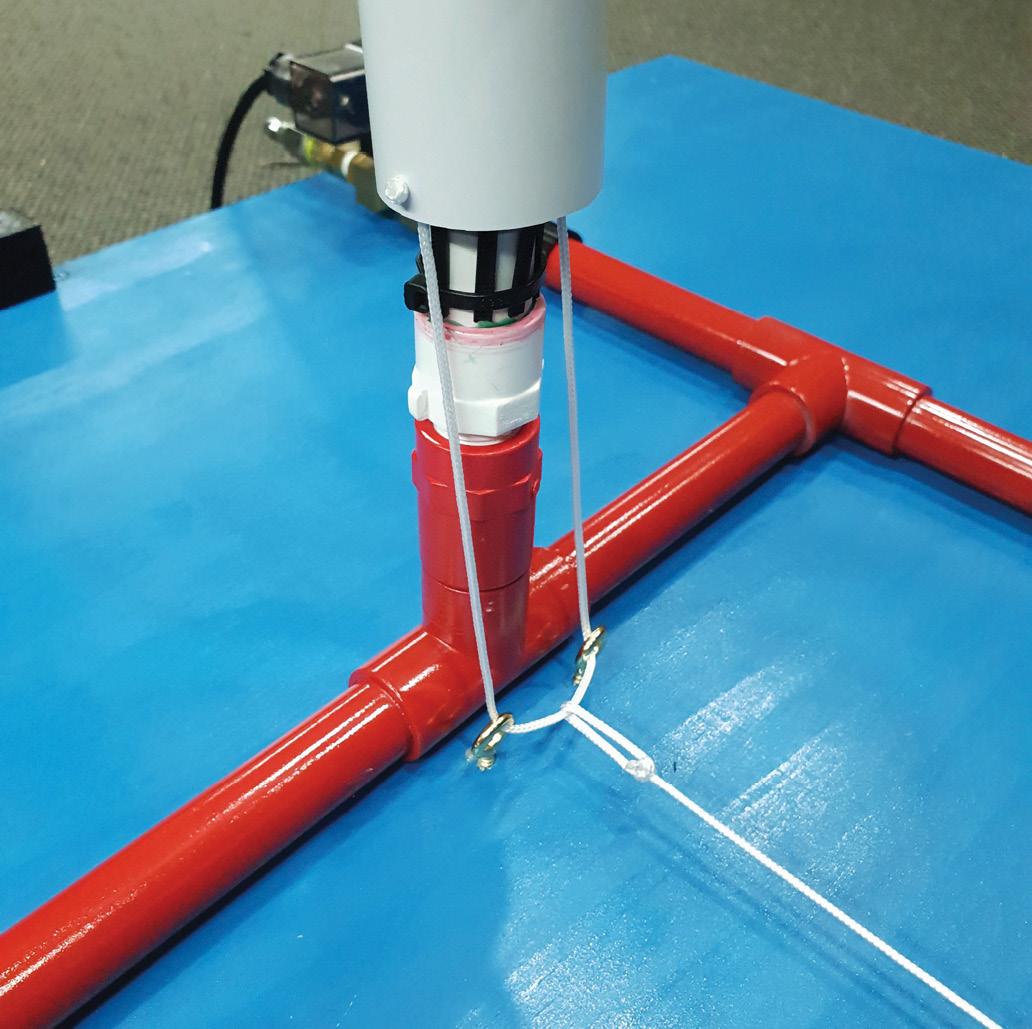
Another length of the same cord is knotted at the end and threaded through the hole in the winch drum. The other end is tied around the loop from the collar. We used a bowline (sort of) so that it can slide to a middle point but any knot you can tie will be ok. The winch can be manually rotated to take up the slack. Note that all photos show the servo exposed. This will be covered by a shield to stop it from getting wet, but that would also obscure it in the photos.
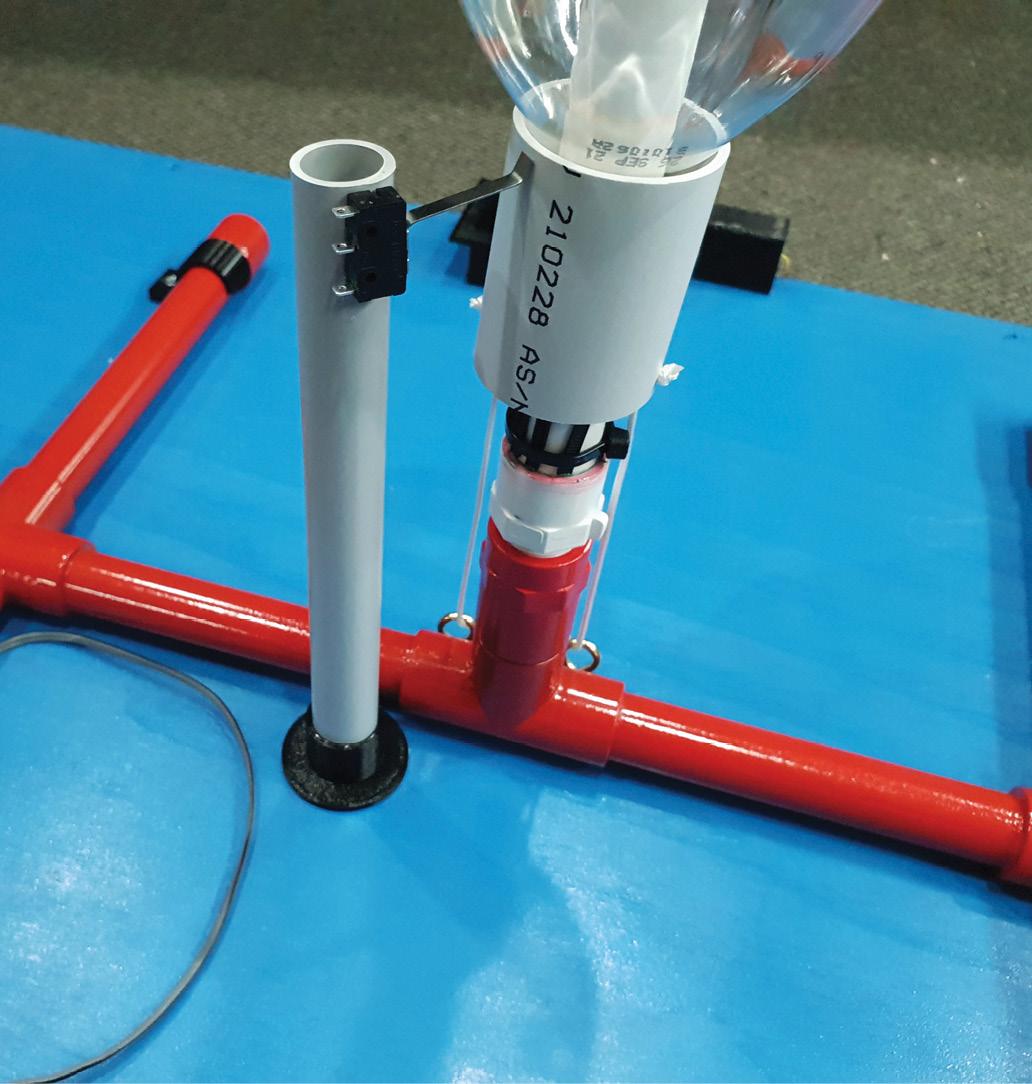
›› The final task was to fit the limit switch for the collar. There is another bracket for this, 3D printed, and it was glued to the base with an appropriate length of 20mm electrical conduit glued in. The limit switch is glued to the top, and the lever is bent outwards to provide a bit of clearance. It is mounted so that the lever is only depressed when the collar is fully home. This switch will get wet and there is little we can do about it, so we used a small amount of glue with the view of replacing the switch when it fails.
SIMPLIFICATIONS
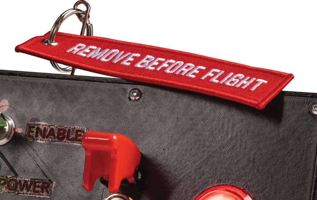
If you don’t have the issues of the public involved, much of this system can be simplified. One master power switch would keep the launcher safe while your face was around it. Good practice and self-checking protocols take care of much of the rest. The launcher itself could be built with the valves, servo, one switch, and of course the ESP8266 for wireless control. The console is much the same. A power switch, arm switch to activate the valves and pressurise the system, and a fire button. However, some of the details are quite fun, like removing the ‘Remove Before Flight’ safety pin from the launcher. And missile Switch covers. Those are always fun!
3D PRINTED PARTS
There are a bunch of 3D printed parts for this project. You can figure most out from the names of the parts or the photos of the build. Most can be printed in any colour, but the light elements for the stack lights should be printed in natural. Also, note the safety pin guide. This tube is glued to the inside of the missile switch panel on the launcher and the inside of the console. It keeps the safety pin in a straight line for impacting the limit switch lever. Everything should print without supports, but some printers benefit from them anyway when printing circular openings.
FUTURE LAUNCHER IMPROVEMENTS
We should have added adjustment holes for the PIRs, but didn’t because of water ingress fears. Really, they should be there and just stay covered with tape. We'll add these to the downloadable files. More time and energy can go into the wiring. If we really had the wait time and could justify the expense, a custom PCB with just terminals for all the incoming wiring, with all the relays, power supplies, and ESP8266 on board, would be awesome. We would also like to modify the unit to use the metal lever release system. The o-ring launcher will happen, one day, when we can find the right materials.
BUILDING ROCKETS
Rockets need to be more than simple bottles, which at these pressures, tend to flip. At a minimum, they need fins. A nose cone helps a lot, too. You could 3D print these, but cardboard is fine for the fins. Nose cones are altogether harder. There are many ways of dealing with this, so we encourage you to research and check some of the linked resources. Rockets tend to work best when long and thin, too. The reasons why would fill the whole article, but the summary is: Because Physics. That’s why you see tiny fins on the fibreglass scratch-made water rockets. We'll go over this further in Part 2.
NEXT MONTH: Part 2 - FINALISING THE BUILD, CODE AND LAUNCHING ROCKETS!