Our friend, Johnny Meccano, has done it again, combining his love of Meccano with electronics. This month, Johnny sent us details on his build and welcomed us to publish it here for our readers.
Usually, we would introduce our maker to you, however, we already introduced Johnny back in Issue 42 with his joystick-controlled Meccano rocket launcher and his Servo Operated Marble Maze in Issue 50 as well. If you want to know more about Johnny, we encourage you to read those previous features.
Let’s get straight into Johnny’s project.
The Mechanical Build:
The Meccano community has an annual Christmas challenge. For 2021, the rules were simply to build a model with road wheels that consisted of part 20 1" Pulleys and part 142 Tyres. This presents a challenge as the overall diameter of the Pulley with the Tyre fitted is only 1½" which makes it a tight squeeze if you wanted to fit a differential.
There was a narrow diameter differential published in the Meccano Magazine in Oct 1976 but it had a locking mechanism that I didn’t need.
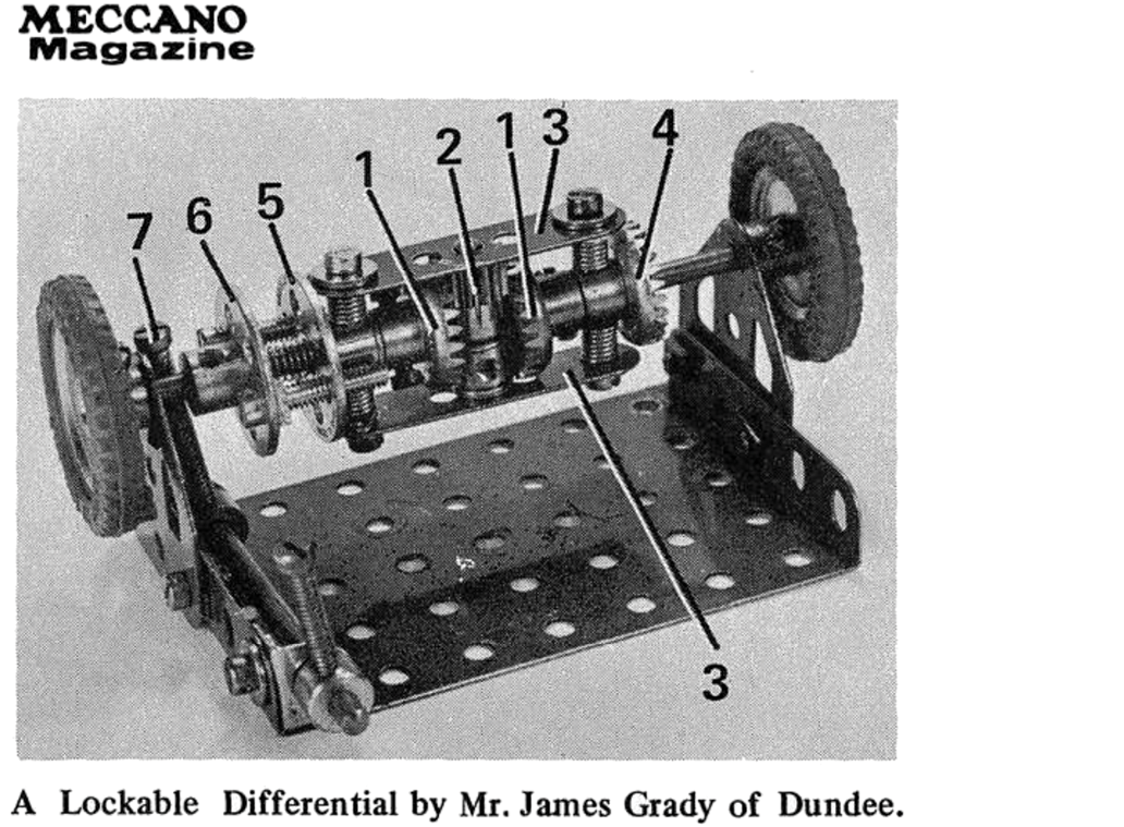
After building it without the locking part I wasn’t happy with its operation as the Cord Anchor Springs used as spacers were distorting when I tightened them and the inner Contrates were rubbing against the Collar so I decided to redesign it.
1st step. Use a rod for alignment. Ensure it’s true and travels freely.
Easy as 1,2,3. Bolt size is M1.6
Getting this diff to run freely requires a lot of sorting through Contrates as they vary a lot. You might notice the Contrate on the left of the Pinion has a slightly smaller crown than the Contrate on the right of the Pinion. The drive Contrate on the very left was the only one in my collection that would allow me to lock the Bolt to the boss without the hex Nut getting fouled by the crown. If you can’t get the hex Nut to turn, try the following alternatives.
The Electronics
We want the car to travel forward until an obstacle is detected then it needs to turn the steering and reverse for 3 seconds. Then it must return the steering to straight ahead and drive forward again. To do this I’ve used an ultrasonic detector available for just a few dollars anywhere that sells Arduino parts. Then a microcontroller is required to read the signal and operate the motor and servo motor accordingly. I used a Nano because I had one spare and I figured small was good. You can just as easily use a Uno. As it turned out I didn’t save much space because it was easier to use a Nano expansion shield than try to solder all those wires in.
Before we get started on the wiring and coding, let’s get all the parts mounted.
For the ultrasonic detector, I found that the 4 header plugs fitted snugly between the Bolts in a part 77 Triangular Plate so I bolted 2 together and squeezed the leads in. (Quite a bit of force was required!) The Plate can then be bolted to an Angle Bracket, which is bolted to the Part 45 Double Bent Strip at the front.
Arduino Nano on an expansion board
H Bridge on perfboard
It would be easy to use a motor/servo shield but after writing the article on how to use H bridges I thought it would be more interesting to grab a L293D H bridge from my bag of goodies and put it on a scrap of perfboard.
Allow 8 holes for the IC pins and 4 more for a 2-way header pin for the motor. You only need to solder one side as we only need 2 channels to control 1 motor.
Note: Don’t take the power for the motor from the expansion board as it only supplies 5V. Take it from the DC socket to get the full 7.4V.
Look at the pinouts to the right. The power for the motor goes to pins 4,5 (Ground) and 8 (+ve). The motor is connected to pins 3 and 6. If Input 1 is set to low and Input 2 high then the motor will run forward. Set Input 1 to high and Input 2 to low and the motor will run backwards. You also need to set pin 1 high to enable both channels but more on this in the section about the sketch, which is Arduino jargon for code.
I left the Tamiya plug on the battery so it can be recharged as normal and piggy backed a right angle DC plug with a micro slide switch on the positive lead.
Mount the 7.4V Li-ion or LiPo battery as shown using a bit of adhesive Velcro. I added another Double Angle Strip to stabilise it.
The home-made perfboard with the H bridge is bolted to the Nano expansion board with M3 bolts. You need to drill the 3mm holes in the perfboard.
The completed assembly slides into the grooves of the two Rubber Pulleys. Make sure nothing is touching the metal before you plug the battery in and switch it on!
Now it’s just a matter of connecting the wires as shown in the Fritzing diagram shown here.
The Nano expansion board can be mounted with part 23c rubber Pulleys which are bolted to the slotted hole on Angle Brackets to allow adjustment. You must use locknuts, or the rubber distorts.
Assembly without the battery attached
The Code
I’m a rank amateur at this Arduino coding but it’s starting to fall into place. I watched Paul McWhorter on YouTube showing how to control a motor with an Arduino and a H bridge. His example was a 4-wheel car with steering done by switching the LH motors forward and the RH motors reverse to turn right. His explanation was enough to figure it out for one motor.
The servo control was simple as I’ve used that before in my Rocket Launcher and Marble Maze. The ultrasonic sensor was foreign, so I just copy-pasted the code from the Arduino website examples. The code is available on the DIYODE website or NZMeccano gallery.